

Introduction
Cutaneous T-cell lymphoma occurs when white blood cells in the skin become cancerous. Mycosis fungoides, a type of cutaneous T-cell lymphoma, causes widespread patches and plaques involving visceral organs [1]. Several studies have investigated treatments for mycosis fungoides, such as chemotherapy and immunotherapy [2, 3]. The total skin electron irradiation (TSEI) technique, which delivers uniform doses to the patient’s skin [4], has been reported to be effective in several previous studies [5]. It is generally accepted that the shielding of very thin organs, such as fingernails and toenails, prevents double exposures, and shielding lenses minimize toxicity [6].
Clinically, the hemi-body irradiation (HBI) technique, which delivers a uniform dose to a part of the skin, has been proposed to minimize dose deposition on the remaining healthy skin [7]. However, the HBI technique primarily uses photon beams with collimators because electron shielding is extremely complicated owing to the electron scattering effect and X-ray contamination [8]. Several studies have been conducted on hemi-body electron beam irradiation (HBIe−) using lead, aluminum, or plywood plates [9–11]; however, they all reported significantly wide penumbra at the shield boundary. Furthermore, a previous study on electron shielding has investigated the effect of surrounding the organs-at-risk with low-Z materials, such as wax bolus [12]. Essentially, minimizing the air gap between the shield and skin could reduce the penumbra width at the electron shield boundary.
In this study, we propose the use of a thimble-like head bolus shield surrounding the patient’s entire head to deliver a uniform dose to the patient’s skin, except in the region above the neck. The feasibility of the head bolus shield was evaluated using the Monte Carlo (MC) method. Subsequently, the shielding performance of the head bolus was measured by comparison with a clinically used lead plate shield.
Materials and Methods
1. Monte Carlo Simulation
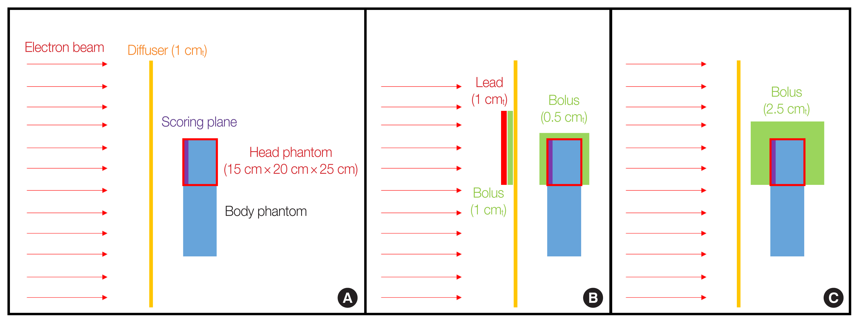
The effects of the lead plate shield and surrounding bolus shield were evaluated to validate the plausibility of the thimble-like head bolus shield using the Geant4 toolkit [13]. The MC simulation was carried out with a simplified configuration. A 6 MeV monoenergetic electron beam of sufficient field size (100 cm×100 cm) for a uniform fluence distribution was irradiated in the anterior-posterior (AP) direction through a 1 cm-thick polymethyl methacrylate (PMMA) spoiler. A water phantom of 15 cm×20 cm×25 cm represented the patient’s head, and an additional water volume below the head phantom was placed to take the scattering from the phantom body into account. In the MC simulation, the electron and photon energy fluences at the upstream surface of the head phantom were evaluated. Additionally, the electron fluence as a function of the distance from the center of the phantom was studied.
The three shielding scenarios shown in Fig. 1 were tested. Fig. 1A illustrates the electron irradiation without any shield except for the 1 cm-PMMA spoiler of infinite area. Fig. 1B shows a 1 cm-thick lead, a 1 cm-thick bolus plate shield upstream of the spoiler, and an additional 0.5 cm-thick bolus surrounding the head. The area of the shielding plate was 32 cm×32 cm, which is the same as that of clinically used shielding plates. This plate is larger than the head phantom to minimize the electron scattering effect on the phantom at the edge of the plate. Fig. 1C shows the configuration used to evaluate the effects of a 2.5-cm thick bolus surrounding the head. The bolus used in this study was composed of Ecoflex 00–30 (Smooth-On Incorporated, Macungie, PA, USA); the properties of the bolus material are listed in Table 1 [14].
Herein, the “G4EmStandardPhysics_option4” modular physics constructor was used for radiation therapy simulation. A total of 5×10⁷ incident electrons were simulated to obtain sufficient statistics with statistical uncertainties of less than 1%, and the simulation took approximately 280 CPU hours for each case.
2. Experimental Configuration
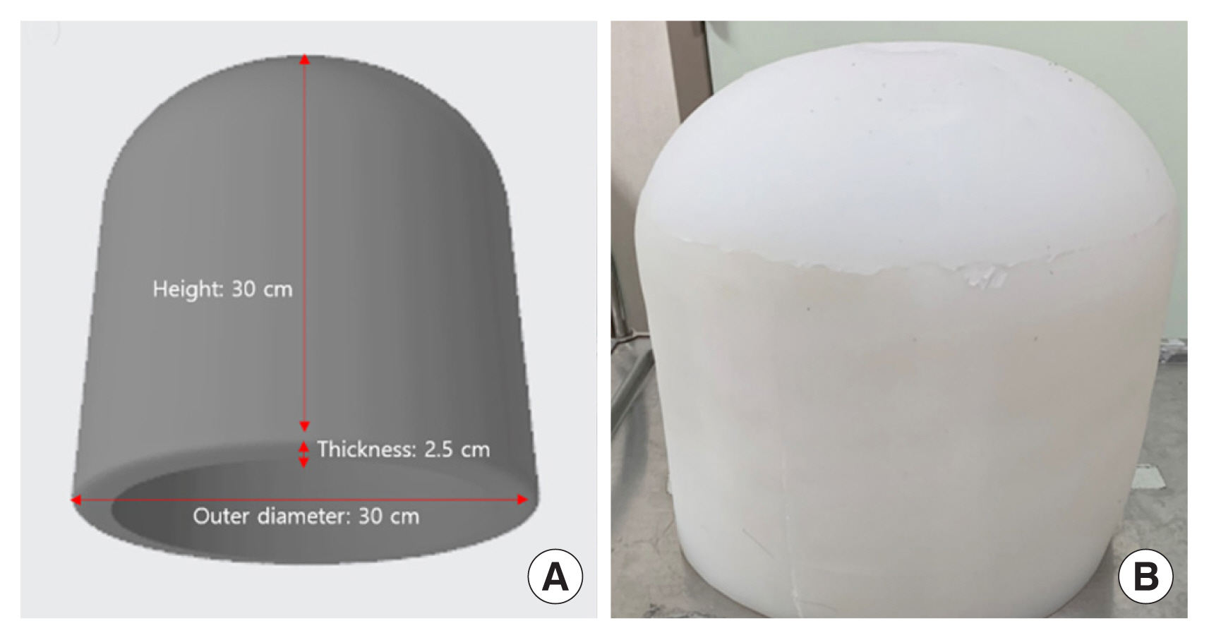
The thimble-like head bolus was manufactured using a three-dimensional (3D) printed mold—M300 dual 3D printer (Zotrax, Olsztyn, Poland) and high-impact polystyrene (HIPS) filament—and Ecoflex 00–30 silicone, as shown in Fig. 2. This head bolus is not patient-specific but has a simple cylindrical shape because of its shielding purpose, unlike the clinical 3D bolus. Note that 3D manufacturing took 249 hours; however, we could avoid the time-consuming procedure of 3D printing for patient-specific devices, leading to approximately 130 hours per case for all patients. A head bolus with inner and outer diameters, height, and thickness of 25, 30, 30, and 2.5 cm, respectively, weighs 4.7 kg.
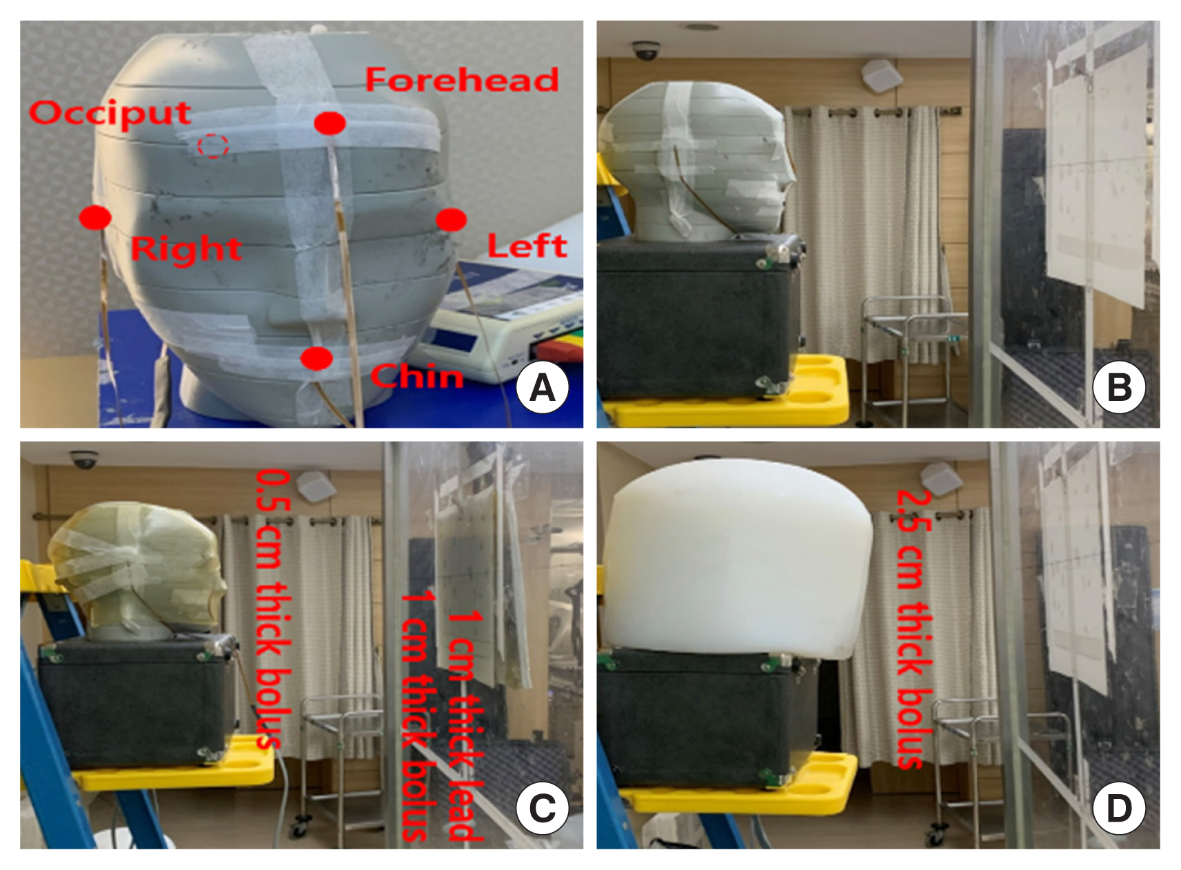
Subsequently, experimental validation of the head bolus was performed using the clinical configuration of HBIe−. The Stanford technique, which is the most typical way to deliver a uniform dose to patient skin using the TSEI technique, was used [15]. TrueBeam linear accelerator (Varian Medical Systems, Palo Alto, CA, USA) was used to deliver a 6-MeV high dose rate total skin electron (HDTSe−) beam of 2,500 MU/min, determined by the monitor unit (MU). The pre-calibrated MU total of 2,178 was irradiated with a 40 cm×40 cm field size and delivered a prescription dose of 200 cGy. An extended source-to-axis distance (SAD) of 340 cm and gantry angles of 90°±19° (i.e., 71° and 109°, pre-calibrated) were used in the dual-field irradiation technique to obtain sufficient longitudinal coverage and dose uniformity.
The Rando head phantom (CIRS, Norfolk, VA, USA) was positioned in six directions (anterior, left anterior oblique, right anterior oblique, posterior, left-posterior oblique, and right-posterior oblique), as described by the Stanford technique [16]. A 1 cm-thick layer of PMMA spoiler reducing the electron range in patient skin was placed 30 cm in front of the phantom to target the T-cells distributed in the cutaneous layer. Measurements were carried out at five locations on the head phantom using a TN-502RD-H metal-oxide-semiconductor field-effect-transistor (MOSFET) dosimeter (CNMC, Nashville, TN, USA), as shown in Fig. 3A. The MOSFET detector was used in high-sensitivity mode, which is three times more sensitive than the standard mode. The MOSFET detector was pre-calibrated using a 6-MeV electron beam in the reference condition to verify the output consistency; However, the dose rate at the patient surface is similar to 6 MeV electron beam owing to the extended SAD configuration. The supporting structure below the Rando phantom was filled with a bolus to consider the phantom scatter effect; nevertheless, the influence on the phantom surface may have been negligible.
In addition to the MC configuration, measurements were performed for the following three shielding scenarios. The first case was the Rando head phantom without any shield but a 1 cm-thick PMMA spoiler, as shown in Fig. 3B. The second case was a 32 cm×32 cm lead and bolus plate upstream of the PMMA spoiler with an additional 0.5 cm-thick bolus surrounding the head phantom, as shown in Fig. 3C. The last case was a thimble-like head bolus of 2.5 cm covering the patient’s entire head, as shown in Fig. 3D.
Results and Discussion
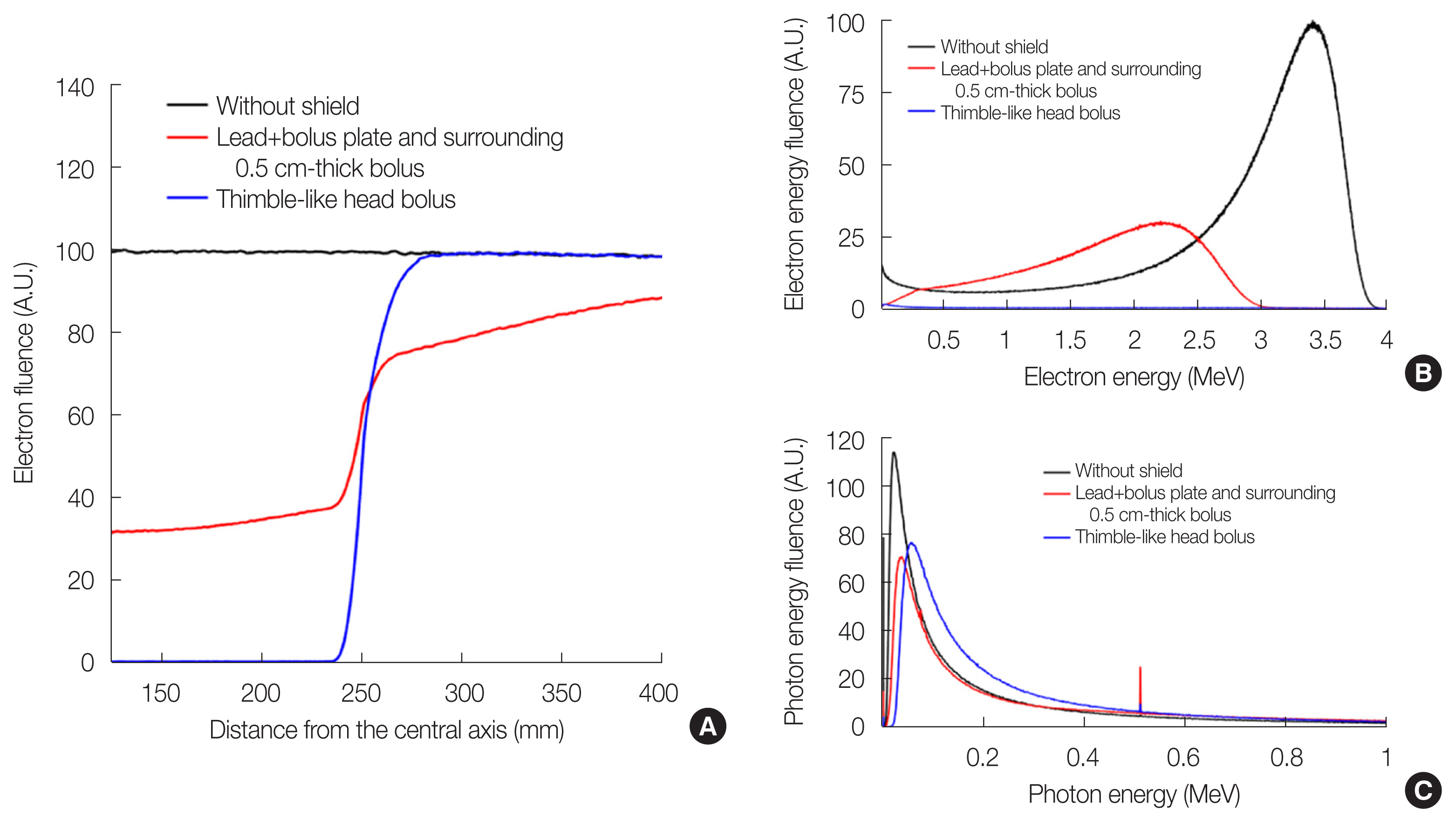
In the MC results shown in Fig. 4, the electron fluence exhibits a uniform distribution along the off-axis distance without the shield. The total thickness of the shield (PMMA of 1 cm thick, lead of 1 cm thick, and bolus of 1.5 cm thick) was sufficiently large to stop 6 MeV electrons. Note that electrons have a practical range of approximately 2.9 cm in water [17]. However, the lead and bolus plate along with the surrounding 0.5 cm-thick bolus blocked only 67% of electrons. In addition, it was observed that the lead shield caused unintended dose decreases outside the shield by down to 25%. We assumed that the disequilibrium of electron fluence due to electron scattering at the air gap between the plate shield and the phantom caused shielding washout. By contrast, the thimble-like head bolus reduced the electron fluence at the head surface to 2%, with a small fluence degradation outside the shield.
Fig. 4B shows the electron energy fluence at the scoring surface. Although the incident energy of electrons is monoenergetic at 6 MeV, a mean energy of 2.8 MeV is evaluated for the PMMA plate scenario. The lead+bolus plate with the surrounding 0.5 cm-thick bolus and thimble-like head bolus reduced the electron flunce and mean energy of electrons to 1.8 and 1.3 MeV, respectively. However, the photon fluence (including bremsstrahlung X-rays and annihilation photons), as shown in Fig. 4C, exhibited no significant differences with respect to the shielding scenarios. Although the bremsstrahlung events occurred in the thimble-like bolus were only 19% of the same events occurred in the lead plate, the photon fluence of the thimble-like head bolus case was 10%–12% higher than that of other cases. Therefore, we concluded that the distance between the bremsstrahlung target and the scoring plane is important because of the directionality of the bremsstrahlung X-rays. However, the contribution of photon fluence to the surface dose was almost negligible, as reported in a previous study [17].
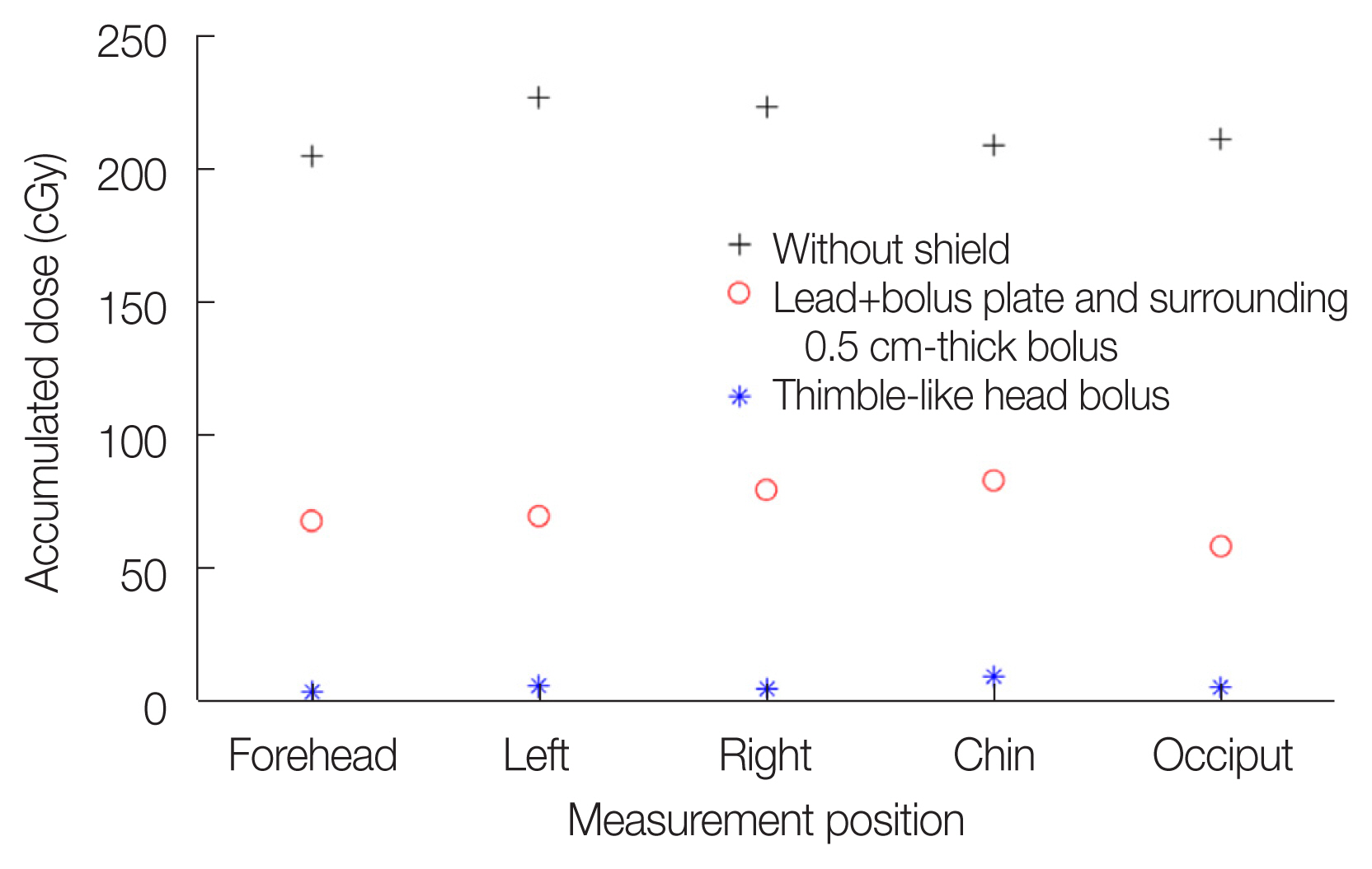
In the experimental study using the MOSFET detector, the average dose of 214.9±9.5 cGy and 71.3±9.9 cGy over five dosimetric points were evaluated for configurations with and without the shielding, respectively, as shown in Fig. 5. The lead and bolus plate with the surrounding 0.5 cm-thick bolus prevented only 67% of the prescribed dose, as in the simplified MC case; therefore, we concluded that the shielding area was not sufficient to shield the entire head owing to electron scattering. However, a larger plate shield may result in an undesirable decrease in the dose outside the shield.
In contrast to the lead shield, 5.3±2.1 cGy was measured over five points with the thimble-like head bolus developed in this study. The shielding performance reducing the dose down to 2.5% was superior to that of the former approach and was consistent with our MC results (2%). Based on these results, we validated the dosimetric characteristics of the thimble-like head bolus for the HBIe− technique. However, for use in clinical practice, the 4.7 kg weight of the head bolus might be a potential obstacle to overcome because it is too heavy to be placed on the patient’s head. From a clinical perspective, fixing the head bolus should be considered for patient safety.
Conclusion
In this study, a thimble-like head bolus shield for the HBIe− technique was developed and validated. In the MC simulations, this bolus shield reduced the electron fluence to 2% compared with that without the shield. This result showed a performance superior to that of the clinically used lead plate shield, which only prevents 67% of electron fluence. In addition, the dose decrease outside the head shield was remarkably reduced. In the experimental validation using the in-house developed bolus shield, this bolus reduced the electron dose to approximately 2.5% of the prescribed dose.