Radiological Assessment of Environmental Impact of the IF-System Facility of the RAON
Article information

Abstract
Background
The evaluation of skyshine distribution, release of airborne radioactive nuclides, and soil activation and groundwater migration were required for radiological assessment of the impact on the environment surrounding In-Flight (IF)-system facility of the RAON (Rare isotope Accelerator complex for ON-line experiment) accelerator complex.
Materials and Methods
Monte Carlo simulation by MCNPX code was used for evaluation of skyshine and activation analysis for air and soil. The concentration model was applied in the estimation of the groundwater migration of radionuclides in soil.
Results and Discussion
The skyshine dose rates at 1 km from the facility were evaluated as 1.62×10⁻³ μSv·hr−1. The annual releases of 3H and 14C were calculated as 9.62×10⁻⁵ mg and 1.19×10⁻¹ mg, respectively. The concentrations of 3H and 22Na in drinking water were estimated as 1.22×10⁻¹ Bq·cm−3 and 8.25×10⁻³ Bq·cm−3, respectively.
Conclusion
Radiological assessment of environmental impact on the IF-facility of RAON was performed through evaluation of skyshine dose distribution, evaluation of annual emission of long-lived radionuclides in the air and estimation of soil activation and groundwater migration of radionuclides. As a result, much lower exposure than the limit value for the public, 1 mSv·yr−1, is expected during operation of the IF-facility.
Introduction
A heavy-ion accelerator complex, named Rare isotope Accelerator complex for ON-line experiment (RAON), is under a construction in Korea for use in basic science research and various applications [1]. In the RAON, an In-Flight fragment target and isotope separator system (IF-system) has been designed to produce and separate interesting isotopes. The IF-system uses heavy-ion beams, from oxygen to uranium, up to 400 MeV/u [2]. Energetic particles including neutrons are produced from the spallation process of the heavy-ion beam and distributed inside the facility. Therefore, radiation shielding design should be applied to protect radiation workers and public in the facility, and radiological assessment of the impact on the environment surrounding the facility is also required according to domestic regulations in Korea [3]. Radiological assessment of the environmental impact for the accelerator facility is focused on evaluation of the public exposure levels for the population near the facility. The exposure paths of the public near the accelerator facility are divided into skyshine, airborne radioactive nuclides, soil activation, and groundwater migration [4].
Radiation facilities are generally designed with sufficiently thick shield to attenuate the dose rate to less than the regulation limit. Because high energy particles are produced from the accelerator, very thick shield walls are installed in the accelerator facility. For instance, an IF-system using a uranium beam at 400 MeV/u requires an approximately 10 m-thick concrete wall to obtain a dose rate less than the public exposure limit, 1 mSv·yr −1, outside of the facility [3]. It is possible to install such thick shields on the walls, but not on the ceiling because of the massive load problem. Therefore, ceilings of accelerator facilities generally have thinner thickness than necessary and neutrons and gammas leak through the ceiling. These neutrons and gammas that leak over the ceiling are scattered in the air and reach the ground. This is called skyshine, and is a significant exposure path for residents near accelerator facilities [5].
During operations, the air inside of an accelerator facility is activated by irradiation of energetic particles, mainly neutrons, which are then discharged to outside the facility. The concentration of radioactive nuclides in the air is controlled by cooling, delaying, and filtering, and must be kept to less than the release limit as set by domestic regulations. The IF-system uses ventilation to reduce the release of airborne radioactive nuclides to less than that limit [6]. Although the amount of radioactive nuclides in the discharged air is expected to be less than the limit of domestic regulations, some long half-lived radioactive nuclides, such as 3H and 14C, might accumulate continuously in the environment. Therefore, their annual releases are generally evaluated to ensure radiation safety for the public near the facility [7].
The soil of the facility site is also activated. Energetic particles, mainly neutrons, penetrate the basement concrete floor and are distributed in the soil region. Then, radioactive nuclides are produced by the neutrons distributed in the soil. Most radioactive nuclides produced in soil remain in place where it was produced, but some mobile nuclides, such as 3H and 22Na, move into groundwater [4]. The migration of the radioactive nuclides to groundwater constitutes an exposure path, through drinking water, for public near the facility.
In this study, evaluation of skyshine distribution, releases of airborne radioactive nuclides, soil activation and groundwater migration were performed as radiological assessment of the impact on the environment surrounding the IF-system facility of the RAON complex.
Materials and Methods
1. Evaluation of Skyshine
The facility model and source terms from the previous study [3, 8] for the shielding design and analysis of the IF-system facility were used in the skyshine calculation. A hemispherical air layer with a radius of 2 km was added in the facility model to calculate the skyshine dose. An air density of 1.205×10⁻³ g·cm−3 is considered in the calculation. Ground is also included in the calculation model. A layer that has a thickness and density of 1 m and 2.2428 g·cm−3, respectively, has been included in the calculation model to represent the ground. The skyshine calculation model is shown in Fig. 1.

(A) Horizontal section view and (B) vertical section view of the skyshine calculation model for the IF-system facility of the RAON (IF-target is at the center of the concentric circles). IF, in-flight; RAON, Rare isotope Accelerator complex for ON-line experiment.
MCNPX version 2.7 code [9] and ENDF/B-VI.8 nuclear data library [10] were used in the skyshine calculation. The dose rate on the ground was calculated every 100 m along the radial direction from the IF-system. Only a few neutrons were scattered in the air and reached the ground level. The scattering reaction rate of neutrons in air is very low because of the low air density. Therefore, Monte Carlo simulation results with poor statistical error were obtained. The force collision option [11] of the MCNPX code was applied in the air layers to improve the statistical reliability by increasing the neutron scattering events. Additionally, geometric splitting [11] was applied in the air layers to increase neutron tracks, over a very long distance of 2 km. As a result, relative errors of neutron flux of less than 4.7% were obtained up to 2 km.
2. Calculation of Induced Activities in Air
The facility model and source terms from the previous study [3, 8] for shielding design and analysis of the IF-system facility were also used in the activation calculation for the inside air. The IF-system facility consists of three regions of the high energy beam transport room, pre-separator room, and main separator room. Each region is closed and sealed during operation by using negative air pressure design for the accelerator rooms. Therefore the induced-activities produced in the air were calculated in each region and the total release of radioactive nuclides was estimated by summing the air discharged from each region. The internal configuration of the IF-system facility and calculation regions for air activation are shown in Fig. 2.
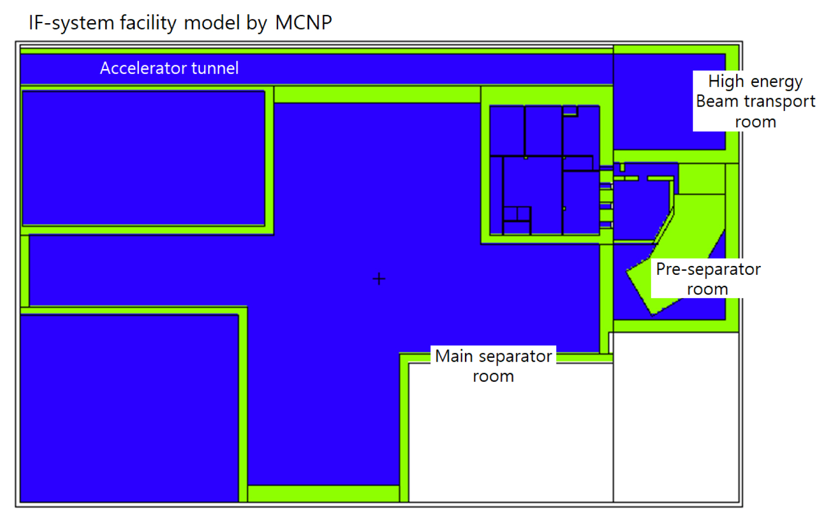
Internal configuration of the IF-system of the RAON and calculation regions for the air activation. IF, in-flight; MCNP, Monte Carlo N-Particle code; RAON, Rare isotope Accelerator complex for ON-line experiment.
Although total annual operation time of the IF-system is 2,000 hours, 200 hours of maximum continuous operation time is applied in the activation calculation for air. The IF-system facility of RAON uses a ventilation system to circulate air inside and decrease the concentration of induced activities in air. However it was assumed in the activation calculation, conservatively, that the ventilation system had not been installed.
MCNPX version 2.7 code and the ENDF/B-VI.8 nuclear data library were used in the neutron transport calculation, the FISPACT-2010 code [12] patched with the function simulating spallation reaction and the EAF-2010 activation data library were used in the calculation of the induced-activities [13]. The spallation reactions in the activation process should be considered because neutrons above 20 MeV are produced in the IF-system [14].
3. Soil Activation and Groundwater Migration of Radioactive Nuclides
The IF-system facility is built on a rock bed of granite and no groundwater flows through the facility site. However, it was conservatively assumed that groundwater flowed under the facility. The ground region, filled with soil, was described in the calculation model as shown in Fig. 1. Soil density of 2.67 g·cm−3 and composition from Table 1 [15] were used in the activation calculation, and it was also assumed that 30% of water was included in the soil. An irradiation history of 50 years with a 2,000-hour per year operation was considered.
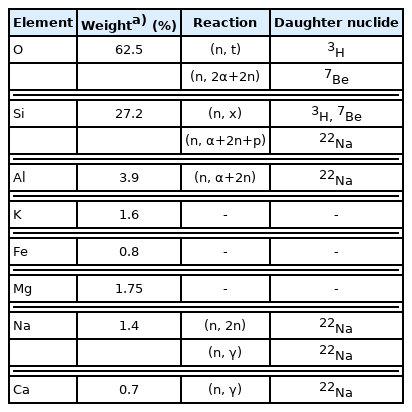
Chemical Composition of Soil at RAON and Nuclear Reactions Producing Dominant Radionuclides
MCNPX version 2.7, ENDF/B-VI.8, FISPACT-2010 patched with spallation reaction function, and EAF-2010 were used in the activation calculation for soil under the IF-system facility. For the evaluation of the groundwater migration of radioactive nuclides, the concentration model was applied [16].
1) Determination of soil activation calculation boundary using 99% volume method
The boundary of the soil activation calculation region was determined using the “99% volume” method [16]. In the 99% volume method, the reaction rate or activity is averaged over a soil volume defined to have its limits at 99% of the total reaction rate or activity in both the radial and depth directions. The activity averaged over “99% volume” is used in the estimation of the initial concentration of the concentration model. The calculation model for the soil activation was shown in Fig. 3. The distribution of the reaction rate in soil was evaluated using the model from Fig. 3 and is shown in Fig. 4. In Fig. 4, cylindrical shaped soil region with radial thickness (or distance) of 9.56 m and depth of 1.8 m was determined as the boundary of the activation calculation. The distance from the IF-target to the outer wall of the facility was about 8.5 m. The dimensions of the 99% volume were evaluated with the RAON facility design values by Monte Carlo calculation.
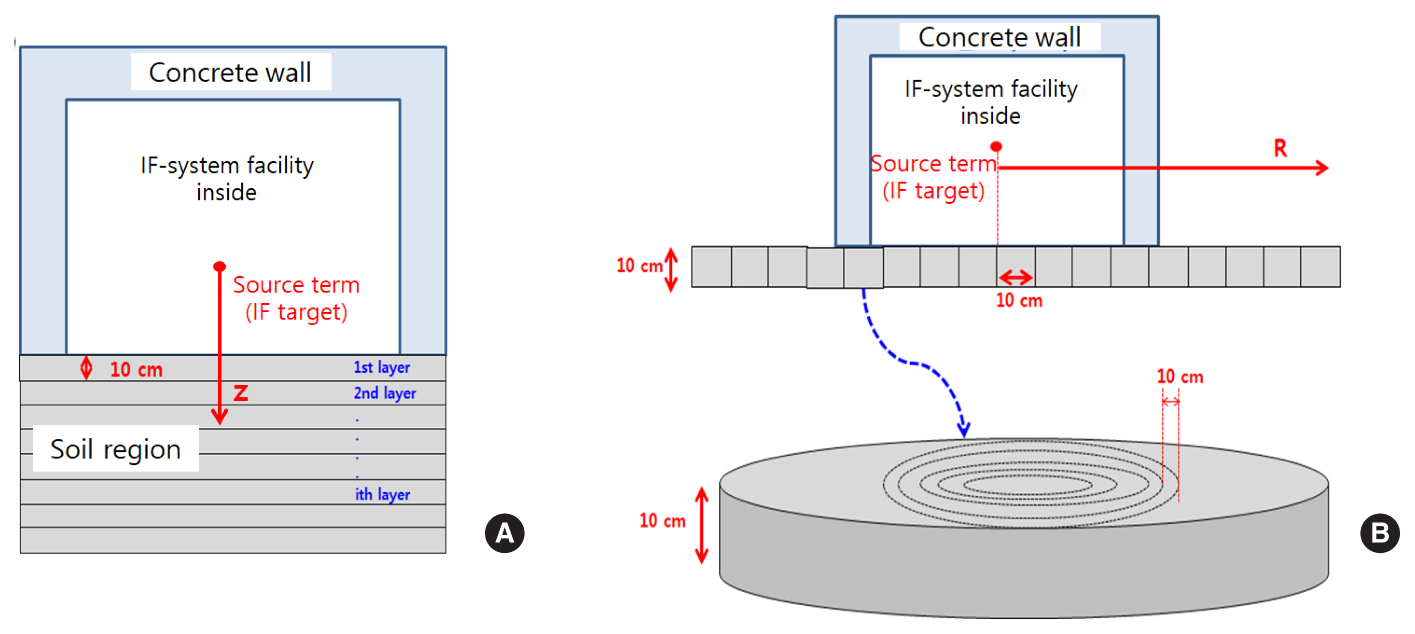
(A) Depth directional view and (B) radial directional view of the soil activation calculation model for the IF-system facility of the RAON (Rare isotope Accelerator complex for ON-line experiment). IF, in-flight.
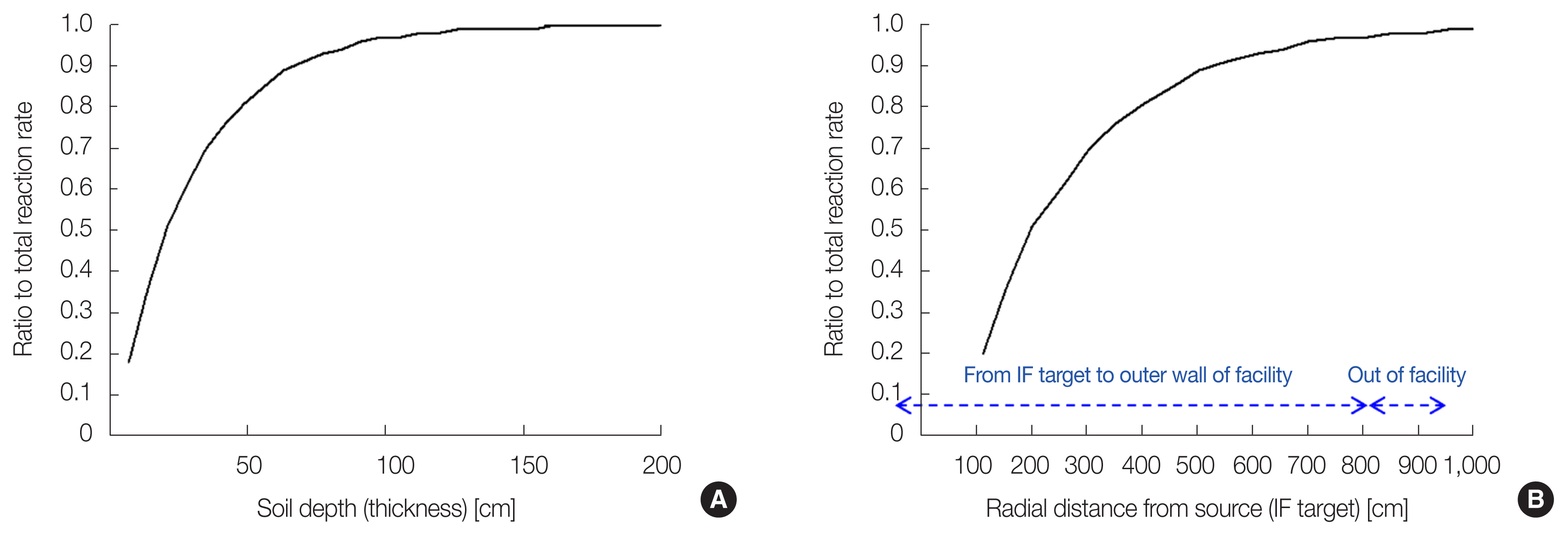
Reaction ratio to total reaction rate in (A) depth direction and (B) radial direction for soil region under the IF-system facility of the RAON. IF, in-flight; RAON, Rare isotope Accelerator complex for ON-line experiment.
2) Migration of radioactive nuclides using concentration model
Naturally percolating groundwater becomes contaminated by leaching out of radioactivity, as it migrates through the soil to the underlying aquifer. 3H, 7Be, 22Na, 45Ca, and 54Mn are known as dominant radioactive nuclides produced in soil. Of these only 3H and 22Na may significantly impact groundwater resources, because of their long half-lives and leachabilities [17]. The concentration model, a mathematical model to estimate migration processes developed for Fermilab [18], was used to determine concentrations of 3H and 22Na in the aquifer. The concentration model calculates an average initial concentration of the i th nuclide,
where,
Sri: production rate of i th nuclide in soil,
Li: leaching factor for i th nuclide (leachable fraction),
t: irradiation time,
τi: mean lifetime for i th nuclide,
ρ: density of soil,
wi: weight of water as fraction of soil weight.
Granite and weathered soil including 30% water in volumetric fraction were applied and the leaching factors were estimated at 0.9 and 0.7 for 3H and 22Na, respectively. The leaching factor from Malensek study [18] was used in this study. The final concentration,
where,
Rt: vertical migration in glacial till from elevation of initial concentration to top of dolomite aquifer,
Rm: mixing with non-radioactive water at glacial till-dolomite interface,
Rd: horizontal transport in dolomite to nearest well or site.
Rt is a reduction factor due to migration and decay during transport to glacial till. Values of 0.4 and 0.06 were applied as Rt for 3H and 22Na, respectively [16]. Rm is a reduction factor due to the mixing of water containing radioactivity with water not containing radioactivity. Rd is also a reduction factor due to migration and decay of specific radioactive nuclides during transport to the nearest well. Both Rm and Rd are conservatively set to 1.
Results and Discussion
1. Skyshine Dose
As can be seen in Fig. 5, maximum dose rates of 0.23 μSv·hr −1 were distributed on the roof of the facility. Target and isotope separation system was installed underground (1st basement floor) and the building consists of three floors above the ground, with a height of 20 m. A thick shield (concrete 1 m and iron 1.5 m) was also added over the target to reduce the dose rate on the ceiling. These facility design characteristics make it possible for a dose rate below 0.25 μSv·hr −1 to be distributed on the outer surface of the facility roof. This means, that, even on the roof of the facility, maximum expected exposure in a year is 0.46 mSv, which does not exceed half the value of the public limit (1 mSv·yr −1). Operation of 2,000 hours per year was assumed. Since the dose rates at the ceiling were already low enough, skyshine dose was also evaluated and found to be very low. Fig. 6 shows the distribution of the skyshine dose rate against the distance from the facility (IF-target). Dose rates at 1 km and 2 km from the facility were evaluated as 1.62×10⁻³ μSv·hr −1 (0.03 mSv·yr −1) and 3.64×10⁻⁴ μSv·hr −1(0.007 mSv·yr −1), respectively.

Distribution of the dose rate inside the IF-system facility. IF, in-flight.

Distribution of the skyshine dose rate against to the distance from the IF-target. IF, in-flight.
2. Annual Release of Airborne Radioactive Nuclides
Fig. 7 shows the activities of radioactive nuclides produced in air inside the IF-facility. Argon-41 is the most dominant radioactive nuclide produced from the neutron capture reaction by 40Ar. Because 41Ar a the short half-life of 109 minutes, the impact on the environment is considered negligible. Although the amounts of 3H and 14C produced are small, they have long half-lives of 12.3 years and 5,730 years, respectively, and can accumulate continuously in the environment. Therefore, annual releases of 3H and 14C were estimated with the activities from Fig. 7. Total operating time of 2,000 hours a year is considered. Ventilation system was applied to the IF-facility, however, for conservative design, reduction of activity concentration by ventilation was not considered in the evaluation of air activation. The maximum annual releases of 3H and 14C were 9.62×10⁻⁵ mg (3.44×10⁷ Bq) and 1.19×10⁻¹ mg (1.96×10⁷ Bq), respectively, as listed in Table 2.

Activities of radionuclide produced in air in the pre-separator room of IF-target facility. IF, in-flight.

Concentration and Release of the Long Half-Lived Radioactive Nuclides, 3H and 14C, in the IF-System Facility of the RAON
3. Migration of 3H and 14C in Groundwater
Results of estimation of radionuclides migration in ground water were summarized in Table 3. In the soil of the IF-facility site, 3H, 7Be, 22Na, 24Na, 45Ca, 54Mn, and 55Fe were produced as dominant radioactive nuclides. Because Be, Ca, Mn, and Fe have no mobility in soil, their migration into groundwater was not considered. 24Na was also not included in the evaluation of groundwater migration because of its short half-life (about 15 hours).
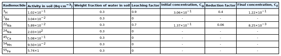
Summary of Radionuclide’s Concentration in Soil and Groundwater by the Concentration Model
With the weight fraction of water (30%) and leaching factors, initial concentrations of 3H and 22Na, in aquifer of soil were estimated as 3.06×10⁻³ Bq·cm−3 and 1.37×10⁻³ Bq·cm−3. The reduction factors during flow through groundwater were 0.4 and 0.006 for 3H and 22Na, respectively. The final concentrations of 3H and 22Na, in drinking water were obtained as 1.22×10⁻¹ Bq·cm−3 and 8.25×10⁻³ Bq·cm−3. The calculated final concentrations were compared to the recommended the World Health Organization (WHO) guidance levels [19] for drinking water (10 Bq·cm−3 for 3H and 0.1 Bq·cm−3 for 14C) according to Equation (4), because there are no legal limits in Korea. As a result, the sum of the final concentration of the IF-facility was lower than the recommendation of the WHO by a factor of 10.
Conclusion
Radiological assessment of environmental impact of IF-facility of RAON was performed through evaluation of skyshine dose distribution, evaluation of annual emission of long-lived radionuclides in the air and estimation of soil activation and groundwater migration of radionuclides. As a result, much lower exposure than the regulation limit for the public, 1 mSv·yr −1, is expected during operation of the IF-facility. Skyshine dose was evaluated as 1.62×10⁻³ μSv·hr −1 at 1 km. Annual releases of 3H and 14C were estimated as 9.62× 10⁻⁵ mg and 1.19×10⁻¹ mg, respectively. The concentrations of 3H and 22Na in drinking water were conservatively estimated as 1.22×10⁻¹ Bq·cm−3 and 8.25×10⁻³ Bq·cm−3, these values are lower than WHO recommendations by a factor of 10.
Notes
Conflict of Interest
No potential conflict of interest relevant to this article was reported.
Author Contribution
Formal analysis: Lee CW. Methodology: Han MH, Whang WT. Writing-original draft, Lee CW. Software: Lee CW. Writing-review & editing: Kim EH, Lee S, Jeong S, Jeong HS.
Acknowledgements
This work was supported by the National Research Foundation of Korea (NRF) grant funded by the Korean government (Ministry of Science and ICT) (No. NRF-2017M2A8A4015251).